1. Introduction
Ocean waves provide an abundant, clean and renewable source of energy. Wave energy can be considered a form of solar energy due to the unequal heating of the Earth´s surface by sun leads to the occurrence of high and low pressures areas. These pressure gradients cause wind; as winds blows over large bodies of water, part of its energy is imparted to the water, resulting in waves; i.e., when wind blows across the sea surface, it transfers the energy to the waves [1-4]. The size and frequency of the waves depend on the length of time, wind speed and distance, known as the fetch, wind blows over the water surface. Long fetches tend to generate the most energetic wave climates. Consequently, coastlines exposed to prevailing wind directions and long fetches tend to have the most energetic wave climates [3-6].
Ocean wave energy has several advantages over other forms of renewable energy as waves are more constant, more predictable and with higher energy densities, enabling devices to extract more power from smaller volumes at lower costs and reduced visual impact [3-7]. In general, wave energy is harnessed by the movements of the device, either floating on the surface of the ocean or operating below the sea level. The energy is captured by oscillating motions at frequency of waves.
Many different techniques to convert wave energy into electric power have been studied in the recent years and, consequently, various types of technologies aiming at harvesting ocean waves have been proposed. Therefore, a number of possibilities are available to date, but no one seems to be predominant and none clearly superior engineering solutions is established yet. In the literature, different classifications can be found; some of them relative to the distance from the shoreline, the generation type or the power conversion are available nowadays [1-3, 8].
For every sea or ocean region around the world, the energy level and properties of the waves are unique. Therefore, it is necessary to design a wave energy converter (WEC) depending on its expected location in order to maximize the energy output at the location. One method for optimizing the design of a given WEC is to optimize its geometric shape, or geometric configuration, so as it will perform to its maximum efficiency in a specified manner. Therefore, in the design, maximizing the power production of the wave energy converters for the majority of the time is required [1-4, 9].
Colombia has a high energy potential due to its geographical and climate diversity across its territory. The energy resource availability of the country could facilitate the incorporation of renewable energy generation market, diversifying the energy matrix [10-12]. In Colombia, according to the Mining and Energy Planning Unit (UPME, by its acronym in Spanish) the dominant source of energy is the hydropower due to its generous hydrology regime and favorable orography provide the basis for a large hydropower potential. It is important to note that a large hydro-based power system may be susceptible to climate variability that could affect the hydrology regime and, therefore, the reservoir capacity of hydropower plants [13-17]. In this regard, new source of renewable energy or non-conventional renewable energies are prudent to be examined in Colombia. In addition, these alternative sources of energy can play an important role in the energy supply for the non-interconnected zones [12-14]. Colombia, today, has many regions with geographical difficulties for extending electricity transmission line, especially those communities located on the Colombian Pacific Coast. Therefore, the absence of reliable power and energy supply is an established challenge to the quality of life of people inhabiting these regions. This is due to most activities are dependent on affordable and sufficient energy for productive processes [18-19].
Nowadays, technologies involving wind turbines, photovoltaic systems, WEC, hydrokinetic turbines and small scale hydropower systems merit more attention from rural electrification programs in developing countries to generate electricity for lighting, refrigeration, irrigation pumping, water supplies, crop processing, agro-industries and small commercial and manufacturing establishments, which use electricity for productive purposes [20-23].
The Colombian Pacific region has immense ecological, hydrographic, mining and forest richness. However, it has low-density population, scarce infrastructure, and some areas do not have electric power supply networks due to the fact that their own geographic, economic and demographic characteristics, among others, the expansion of the networks to the national interconnected system do not have environmental and financial viability. According UPME, energy generation in the non-interconnected zones of the Colombian Pacific Coast relies mainly on diesel technologies, followed by small hydroelectric plant, hybrid and photovoltaic systems, wind power and biomass [17-19, 24].
Due to the large extent of geographic area, the dispersion and small size of communities in the non-interconnected zones, no detailed statistics on energy consumption in households and energy requirements of these areas are still provided. Therefore, initiatives to improve the quality of services provided in these regions, increasing energy coverage and promoting a penetration increase of renewable energy sources would have to depend on the electricity generation in mini-grids or individual solutions.
Under this scenario, in this work, a WEC, which converts the displacement motion of the buoy into electric energy, has been developed for communities located on the Pacific Coast of Colombia. The work is focused on the development of a dynamic model for predicting the WEC power capture as a function of the wave energy spectrum and geometry of the buoy and the linear generator. With the aim of gaining insight into the performance of the WEC, numerical modelling was applied in this work using the software Ansys Aqwa®. The numerical model simulated the behavior of the WEC in the time domain by considering the wave excitation forces, the radiation forces produced by the WEC itself, the hydrostatic restoring forces and, very importantly, the forces in the power take-off (PTO) system.
2. Methods and materials
2.1 Wave energy
The commonly method used for describing the energy in real sea waves is the wave energy spectrum (S(f)). This is a distribution of the wave energy of a given location as a function of the wave frequency (f). Two main parameters were used to describe the wave power (P): the significant wave height (Hm) and the average wave period (T). Hm is calculated as described in Equation 1. The term Hm is often used to describe the height of a spectrum and is defined as the average height of the highest one-third wave in a wave spectrum. This means that Hm is the mean value of the highest 33% of the waves [25] and can be calculated using the Equation (1).
Where m o is the integral of the wave energy spectrum, which is provided by Equation (2) [25].
The total stored energy (E) in a wave per unit area of the sea surface is the sum of the kinetic and potential energy. The potential energy of the wave is due to the elevation of water from the waves trough up to the crest. E can be expressed in terms of Hm and S(f) according to Equation (3) [25].
where ρ refers to the density of the fluid and g is the acceleration due to gravity.
The wave power level (P) per unit width in a wave is given by Equation (4). P is generally proportional to Hm squared [26].
where v g (f) is the group velocity, which is expressed as Equation (5) [25].
WEC captures the energy contained in ocean waves and uses it to generate electricity, as mentioned above. There are three main categories; oscillating water columns that use trapped air pockets in a water column to drive a turbine; oscillating body converters that are floating or submerged devices using the wave motion (up/down, forwards/backwards, side to side) to generate electricity; and overtopping converters that use reservoirs to create a head and subsequently drive turbines. On top of that, each category can be subdivided according to the technologies used to convert wave energy into pneumatic/mechanical energy (rotation/ translation), their power systems (air turbines, hydraulic turbines, hydraulic engines), their structures (fixed, floating, submerged), and their positioning within the ocean (shoreline, near shore, off shore) [26-28].
In this work, a WEC with oscillating body converter was designed due to one of the advantages of floating devices over fixed devices is that they can be deployed in deeper water, where the wave energy is greater. In this regard, designing the geometric configuration of the converter depending on its expected location is required in order to maximize the energy output at that location.
2.2 Device operation
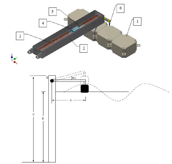
In Figure 1, the conceptual design of the device can be seen. When an incoming wave reaches the buoy, it is displaced throughout the z-axis direction a distance equal to the wave amplitude. The arm is pivoted at D point; so that the vertical movement caused by the incoming wave produces a rotational movement of the arm. This rotation generates an angle (θ (t)) measured between the calm water level and the arm position; this angle is a function of time and the incoming wave amplitude; it is directly the responsible to generate the electric power.
The design of the converter shown in Figure 1 allows its location at the shore and can be placed above the sea (in shallow water), integrated in a breakwater, in a dam or fixed to a cliff. The main advantage of this converter is its ease of maintenance and installation since in most cases the location is accessible. Moreover, they do need neither mooring systems nor a long length of sea cable to connect the WEC to the electric grid. However, at the shoreline, waves contain less energy because of their interaction with the seabed. On the other hand, the lack of suitable land sites also can cause difficulties for deploying this system [25-28].
The linear generator proposed here is composed of three parts: a stator, a translator and guides. The generator is inside the arm body, so that the inclination angle of the arm is the same as the generator. The translator moves along the guides, so when the inclination angle reaches the specified value (ϕ), the movement of the translator becomes imminent, according to the theory of dry friction [29]. The translator has the permanent magnets with the magnetic domains disposed in alternated form (N-S-N). The movement of the translator along the guides causes a temporally change of the magnetics domains; according to Faraday´s induction law, this variation causes an induced current at the stator´s coils. The minimum angle that causes the movement of the translator (ϕ) depends on the static frictional coefficient value, which will be shown in the next section. As the wave passes through the buoy, the process described above is repeated but, in this case, in the opposite direction.
Figure 1
Wave energy converter system. At the top, a detailed design of the device proposed in this work can be seen: 1) Floating buoy; 2) External case; 3) Stator´s coils; 4) Translator; 5) Translator Guides; 6) Arm - Buoy Joining. The parts from 2 to 6 constitute the arm. In the bottom, a sketch of a functioning WEC system is illustrated
2.3 Material
The environmental conditions play a fundamental role in the selection of the materials that will constitute the parts of the design proposed. Due to the exposition to sea water, the arm parts; especially the part housing the generator, were made of AISI 316 steel, owing to anticorrosive properties that this material exhibits under marine conditions. On the other hand, due to the generator is isolated from the external atmosphere, for manufacturing the guides and the external housing, AISI 1020 steel was used. Regarding the stator´s coils, magnetic wire reference 14 AWG was used taken into account that the power generated is aimed at household consumption. The buoy used in the system corresponded to the floating dock commercial modules Candock®, which can provide unlimited configurations for the floating surface; i.e., the floating cubes can be assembled to create the desired shape and size. The blocks were held together tightly and firmly with special connecting pins. All parts were lightweight and easy to handle. They were made of high density polyethylene resin. It is noteworthy that Candock® cubes are remarkably resistant to impact, climate change and the adverse effects of water.
2.4 Dynamics modeling of the WEC
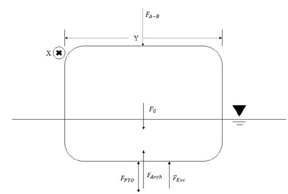
A buoy can be continuously floating in the ocean and undergo a large amount of dynamic motion, which could be feasibly harnessed for power generation. A schematic view of the buoy in the ocean is given in Figure 1. Due to the wave action, the buoy has a position Z from its equilibrium position. Taking the vertical direction like z-axis and analyzing the movement at this direction; Newton´s second law for the buoy motion can be represented as Equation 6 [2-4, 30].
where m
B is the mass of the buoy including all the internal components; FG is the gravity force equal to m
Bg; g is the gravity; Z is the vertical displacements of the buoy and  , the buoy acceleration at z-axis. Additionally, the variable FExc in Equation (6) is the excitation wave force. This force corresponds to the effect of the wave acting
on a body in the water. FExc can be separated into three components: (a) the Froude-Krylov
force (FFK), (b) the diffraction force (FDiff), and (c) the radiation force (FRad).
FFK, produced by the wave momentum, is imparted onto the submerged body. In turn,
FDiff and FRad come from the disturbances to the surrounding fluid [1-3, 31]. Because of the contribution of the diffraction component has significantly smaller
order of magnitude compared to the other two components, the effect of this force
component can be considered as negligible for this analysis. This approximation generally
is known as the Froude-Krylov approximation, which is quite useful taking into account
that the calculus of diffraction component is quite complicated [3-6, 32]. Thus, FExc is determined by Equation (7).
As mentioned above, the diffraction component is equal to zero in this analysis; then, the new expression for FExc is expressed by Equation (8).
The Froude-Krylov component corresponds to the force that the floating body experiences when it is fixed in a mean position and the incoming wave impacts with it [2-5, 32]. The mathematical expression for this component is summarized in Equation (9).
Where hExc is the excitation force impulse response function, which is of non-causal nature [10, 29]. The non-causality implies that the movement of the buoy is not due to the wave that is just passing underneath it, it may be an effect of the wave that is 30 m away the buoy and still has not reached the buoy or a vessel to thousands of kilometers [32]. τ is the wave period. nw is the water free surface elevation that is a function of the period (τ). Furthermore, hExc is a function of t - τ; this indicates that the system is time-invariant linear system. This fact means that the system has the same characteristics now as in the past and in the future [25].
The solution in time domain of Equation 4 is represented by Equation (10).
where the symbol  indicates the convolution between h
Exc
and n
w
.
In general terms, F
Rad
is the force that the body experiences, owning that itself movement causes radiated
waves in the water, which in turn exert a force in the buoy body [32]. This component is divided into two components. The first component is related to
the effect caused when the buoy oscillates ostensibly, leading to a large water added
mass; this component interrelates the added mass  with the body acceleration in this case, the z-axis acceleration
  . The second component is related to the power that the body losses when generating
the water waves; this component interrelates the body velocity
  with the hydrodynamic damping coefficient (K
Hyd
) [33, 34]. The added mass
  physically represents an additional weight of the buoy due to the water surrounding
it. Meanwhile, the hydrodynamic damping (K
Hyd
) physically represents a damping effect, which is a product of the water viscosity
acting over the body oscillation stopping it. Equation (11) corresponds to the equation that represents F
Rad
.
Equation (12) expresses the temporal solution of the integral in Equation (11).
Substituting Equation (12) into Equation (11), the radiation component expression is obtained (Equation (13)].
Therefore, substituting Equation (10) and Equation (13) into Equation (8), F Exc is determined by Equation (14).
Moreover, F arch is the buoyance force acting on the buoy. The Archimedes’ principle says that the buoyancy force that act in a submerged body is equal to the weight of the displaced fluid volume; and it can be located at the centroid of the displaced volume. According to this principle, the buoyancy force can be calculated as indicated in Equation (15).
where g is the gravitational acceleration.
Analyzing the buoy of the device designed, using Figure 2, it is evident that the floating body has a prismatic shape; thus the volume of the fluid displaced has a variation in time. This can be expressed as Equation (16).
In Equation (16), X, Y and Z (t) are the submerged width, depth and the height, as illustrated in Figure 2. Now, substituting Equation (16) into Equation (15), the buoyancy force as a function time is represented by Equation (17).
In Figure 2, the forces on the buoy can be observed; F Exc changes in magnitude and direction with time as PTO force. Nevertheless, in the sketch, the direction of these forces have been defined, but it is only representative.
In turn, the term F PTO is the force associated with the PTO system, which corresponds to the force that the power take-off exerts on the oscillating buoy. When a lineal control is estimated to the take-off system of a wave energy converter, F PTO is modeled as a mass-spring-damper system. The equation governing the behavior of the system is a second order lineal equation [5, 32]. The PTO force can be calculated as expressed in Equation (18).
where R PTO and S PTO are the damping mechanical coefficient and the stiffness coefficient, respectively, associated with the PTO system [5, 25]. As observed in Figure 1, for the device proposed here, the transformation system of wave energy into electricity does not have connection with the buoy; therefore, this term is negligible in the dynamic analysis of the system presented in this work.
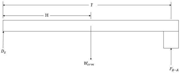
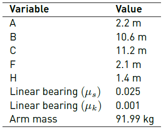
Finally, F B-A in Equation 1 is the arm buoy force. This force is due to the effect that exerts the arm weight (W arm ) on the buoy. In order to know the value of this parameter, a static analysis is conducted from Figure 3. The values of the distances F and H, as well as the arm weight, are compiled in Table 1. From the static equilibrium, applying the torque summation to D point, Equation (19) is obtained.
From Equation (19), the value of F B-A is found using Equation (20)
According to Newton´s third law, the force that the arm exerts on the buoy has the same value and inverse direction to the force that the buoy exerts on the arm; therefore, the expression determining the effect that the arm exerts on the buoy is represented by Equation (20).
Now, when Equation (14), (17) and (20) are replaced in Equation (6), the equation of the buoy motion can be rewritten as Equation (21).
When the effect due to gravitational force on the float and the buoyancy force are unified, a new force (F res ) is generated, which can be calculated using Equation (22) [5, 34, 35].
where K res is called “hydrostatic restoring coefficient”, whose value can be calculated by Equation (23).
A proy corresponds to the perpendicular area projected by the buoy at the XY plane. Now, by substituting Equation (22) into Equation (21) and analogous terms are grouped, the equation of the buoy motion is, finally, Equation (24).
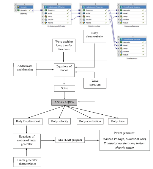
Equation (24) corresponds to the equation that describes the temporal behavior of the device presented in this work. In order to know this behavior, Equation (24) should be solved by using numerical methods. Several software packages can be used to find the behavior of floating buoys under the effect of an incident wave; some of them are open source codes, others are packages under license. In this work, to carry out the numerical modelling of WEC, Ansys Aqwa® package was used to find the response of the buoy under swell specific conditions of sea in the Colombian Pacific Ocean. The software Ansys Aqwa® has different modules to carry out frequency and time domain analyses of marine structures. The elements of the WEC were treated as diffracting elements, so the support was configured to be fixed in a place. Once the WEC geometry was meshed, the frequency-dependent hydrodynamic coefficients were obtained using the hydrodynamic diffraction module and they were stored in a hydrodynamic database. Then, the coefficients were used to solve the dynamic equation of the WEC (Equation (24)] in the hydrodynamic time response module.
2.5 Dynamic analysis of the linear generator
To harvest the wave energy and convert it into electric energy, transforming the wave movement in a relative movement between the coils and the permanent magnets is required. For this purpose, several systems have been developed. Generally, these systems have a mechanism that transforms the buoy displacement into rotational movement. In this regard, recently, the development of systems that take advantage of the buoy movement without requiring an intermediate mechanism has taken force in the electric power generation from waves. These devices are known as linear generators. As the conventional rotatory generators, these machines work under the Faraday´s Induction law. When the translator moves, a magnetic domain change with time is observed, which produces an induced current in a loop of conductive material, according to the mentioned law. In the dynamic model shown in Equation (24), the mass of the translator was considered as negligible for this analysis in comparison with the mass of the rigid arm.
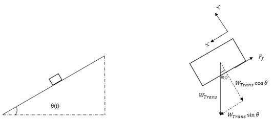
The linear generator proposed here works using the principle of inclined plane. To deduce the equations, Figure 4 is employed. In the figure, the working principle of linear generator is illustrated. When the inclination angle (θ) (t) reaches a determined value (ϕ), the movement is imminent. θ (t) was obtained from submerged height Z (t), which can be found from Equation (24). In accordance with the dry friction laws, this angle is known as “angle of repose”. This angle is only a function of the static friction coefficient and it can be defined as Equation (25).
where µ s is the static friction coefficient. This corresponds to the resistance that should be overcome to begin the movement of a body respect to other one [29]. This coefficient is caused by the irregularities between the surfaces in contact, and it is independent on the magnitude of the contact surface area. Therefore, the unique variable of interest is the static friction coefficient. In order to facilitate the movement of the translator along the guides, the translator has two pairs of linear bearings in contact with the guides, minimizing the static friction coefficient [Table 1] and, subsequently, the value of , so that harvesting any wave elevation.
Nevertheless, when the movement begins, the translator movement is governs by the Newton´s second law. According to Figure 4 and the reference system given, the expression for the movement is represented by Equation (26).
where m Trans is the mass of the translator and a x' is the acceleration of the translator throughout x’-direction.
The force responsible for the movement of the translator is the component of the weight throughout x’-direction, as presented in Figure 4. Hence, Equation (26) can be written as Equation (27).
In Equation (27), µ k is the dynamic friction coefficient whose value is given in Table 1. As W Trans is equal to m Trans g, simplifying this expression, ax' is represented by Equation (28) .
Considering the kinematics of rectilinear motion, the equations for velocity and the position for the movement of the translator are represented by Equation (29) and (30), respectively.
Finally, for calculating the electric power produced, according to Montoya-Andrade (2014), the instant electric power generated is determined from Equation (31) [32].
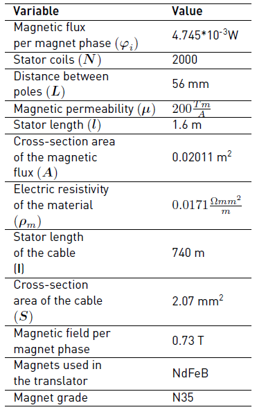
where φ is the magnetic flux, which is equal to N φi , being φ i the magnetic flux per magnets and N the number of coils of the stator. L is the distance between poles of the same polarity. These values are given in Table 2. The power depends on the current (i line ) and the amount of resistance present in the system. A winding of an electric generator can be represented as a RL equivalent circuit. If a RL circuit is considered as a system with input and output, the input is the voltage drop (Vϵ(t)) across the circuit and the output is the current (i line (t)) through the circuit. Both parameters are variable in time. Vϵ(t) across the circuit can be expressed as Equation (32).
By Ohm’s law, i line can be expressed as Equation (33).
Where R T is total resistance. It can be expressed as Equation (34).
Where R g is the resistance of the stator, j is the imaginary unit, and L g is the inductance of coil. The calculation of inductance of coils is based in empirical formulations; therefore, the values obtained are approximate [34]. The inductance can be determined by Equation (35).
In Equation (35), µ represents the magnetic permeability of the coil core, here it is assumed to be made of AISI 1020 steel; N is the coil number; l is the length of the coil and A refers to the cross-section area to the magnetic flux. These values are given in Table 2.
On the other hand, the resistance of the stator can be also determined by using the Ohm´s law. The resistance can be calculated as Equation (36) [36].
In Equation (36), ρ m is the resistivity of the material, l refers to the cable length and S is the cross-section area of the cable. In Table 2, the values of these variables for the device proposed are presented.
3. Results and discussion
As mentioned above, to know the temporally behavior of the wave energy converter proposed
here, Ansys Aqwa® package was used. Aqwa is a BEM code based on the principles of linear wave theory,
so the frequency-domain response has the assumptions of incompressible, irrotational
and inviscid flow. The WEC system shown in Figure 1 was modeled in Ansys Aqwa®. In the software, first, a hydrodynamic diffraction simulation was executed in order
to know the values of the  , hydrodynamic damping coefficient and F
FK
, and its variation in the frequency. Secondly, a hydrodynamic time response simulation
was executed to know the behavior in time of the buoy. Finally, with the elevation
time results, a Matlab® routine was implemented to determine the power electric generated. However, it is
highly important to know the sea conditions in the Colombian Pacific Ocean first of
all. For this purpose, studies on the spectral wave condition in the Colombia Pacific
Ocean were consulted. For example, Portilla et al., in 2015, carried out a research with the purpose of characterizing the specific
conditions of the swell near to the Colombian Pacific coast [37]. To do this, authors analyzed the time records of 4 buoys owned by DIMAR (Dirección General Marítima de Colombia) located along the Pacific coast. The buoys are part of a local monitoring network
that has been working since 2009. The system has several gaps due to failure or maintenance
troubles. These buoys are moored near to continental shelf at Tumaco (Nariño); Gorgona
Island (Cauca); Buenaventura (Valle del Cauca) and Bahía Solano (Chocó). The length
of the record is 30 min with intervals of 1 h between records.
From the measures of the spectrum conducted by other researchers [37], it was found that the swell is constituted mostly by 129 frequencies from 0.0 to 0.64 Hz; distributed at regular intervals of 0.005 Hz. Subsequently, the data were statistically treated to obtain the statistical-geometric description parameters. The locations and values are given in Table 3.
Regarding to the wave direction, from the analysis of the swell accomplished by other researchers [37], the dominant swell direction on Colombian Pacific Ocean was found to be 60° from the Equator. On the other hand, it is important to know which places have potential to generate electricity from the exploitation of the energy from waves. Osorio and co-workers conducted an exhaustive evaluation about the possible kind of ocean energy that can be harvested and the locations along the Colombian coast where these energies are available [38]. From this study, it can be concluded that at the Colombian Caribbean coast, the ocean energy to be exploited is mainly the salinity gradients. Near to the coast of San Andrés Island, thermal gradients can be a good option to generate electricity. Finally, regarding to the Colombian Pacific Coast, the energy of waves and tides can be used to produce electric power. In the current work, the parameters given in Table 3 were used to determine the behavior of the device designed. To carry out the simulations, Bahía Solano conditions were chosen; due to Chocó is a department that adjoints with the Pacific Ocean and a high percentage of its population is not connected to the national electric interconnection system.
To know the behavior of the WEC in Ansys Aqwa®, executing a Hydrodynamic Diffraction analysis is required first with the final purpose to determine the variation of the effects on the buoy with the frequency. To carry out this simulation, mass properties of the bodies should be configured at the center of gravity of each body. The connection between the support and the arm was configured as a kinematic pair of revolute, in order to the arm rotates around the connection point, as it was exposed in the operation of the system. Lastly, the arm was defined as a body free to move, and the support was fixed in a place. In this study, the frequency domain was setup to embrace the interval of frequencies proper of the Pacific Ocean. Likewise, the direction of the waves was configured to be 90° perpendicular to the buoy. The computational procedure employed in this work can be outline as observed in the flow chart of Figure 5.
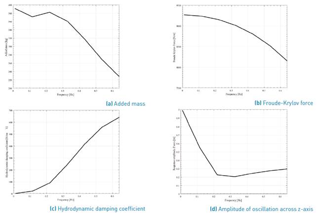
Figure 6 shows the results of this simulation. Figure 6a) corresponds to the variation of the added mass with the frequencies. As observed, the value of the added mass decays with the increase of the frequency. The added mass physically represents an additional force that opposes the movement. A desired result is that the value of this mass is as small as possible. From Figure 6a), it can be concluded that higher values of frequency will lead to a better performance of the device.
In turn, Figure 6b) represents the variation of Froude-Krylov force with the frequency, being the force on the buoy major for small frequencies. Therefore, the minimum value is 8100 Nm-1. It is important to note that this force is related with the wave amplitude; for this reason, it has Nm-1 units. Under lower frequencies, the Froude-Krylov force is higher, which in turn causes an increase in the vertical movement of the buoy and, subsequently, in the angle within the XY plane. This causes that the velocity of the translator is higher as well as the electric power generated. Figure 6c) illustrates the behavior of the hydrodynamic damping coefficient; as it can be observed, this coefficient is higher under high values of frequency; then, working at lower frequencies is preferred. Finally, in Figure 6d) the buoy response amplitude across z-axis is presented; this figure supports the conclusion previously mentioned related to the device working under the effect of lower frequencies. For Joaquín and coworkers, the punctual absorbers work better when their natural frequency is in resonance with the wave frequencies, which suggest that the natural frequency of the device is around 0.1-0.2 Hz [39].
Fusco et al., found that the low frequency components of the wave spectra are the most interesting from an energetic point of view, as a very significant portion of the wave energy is usually concentrated at low frequencies. In addition, with respect to high frequency components, low frequency waves are more regular and less affected by nonlinearities, so that they can be predicted more accurately [40].
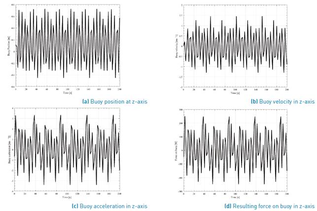
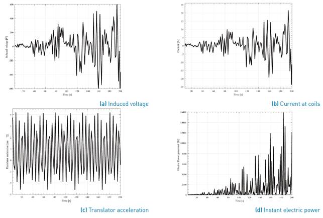
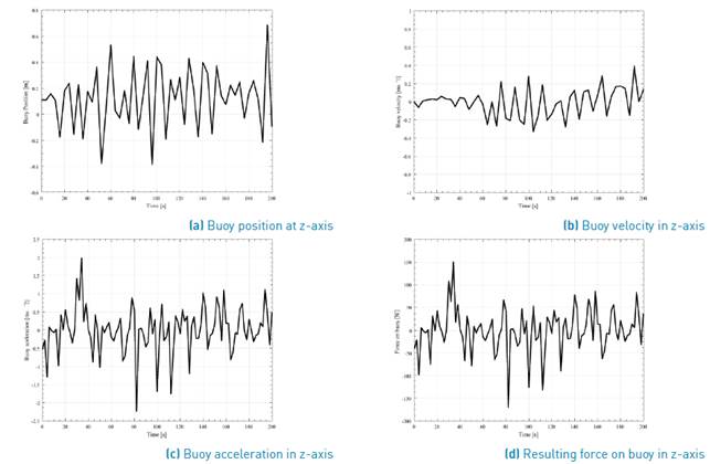
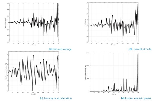
Previously, the results of the hydrodynamic diffraction analysis were presented; now, the results of the hydrodynamic time response are analyzed. In this simulation, a temporal domain of 200 s was used. Two simulations were carried out taking into account, as swell parameters, the significant wave height and the zero crossing period. These data are given in Table 3 for the case of the buoy in Bahia Solano. The first simulation allows knowing the behavior of the system under the effect of Airy wave theory. In this study, the response at a representative frequency of the interval is analyzed, being 0.32 Hz the mean value, in this case. For the second study, the effect of an irregular wave on the buoy was evaluated. For this purpose, an irregular wave spectrum was setup; here, the Pierson-Moskowitz spectrum was used since according to Joaquin and coworkers, it is the most adequate to sea conditions of swell produced by wind and completely developed [39]. This kind of swell corresponds to the conditions exhibited in the Colombian Pacific Ocean [37]. The Pierson-Moskowitz spectrum is formulated in terms of the two parameters of significant wave height equal to 1.17 m and average (Zero Crossing Period) wave period equal to 10.61 s. P in a regular wave, using the Airy wave theory, was equal to 2.504 kW/m; on the other hand, using Pierson-Moskowitz spectrum for the case of an irregular wave, the value of P was equal to 7.97 kW/m. The results concerning the variation of velocity, acceleration, resultant force and elevation of the buoy are shown in Figure 7 and Figure 9, for regular and irregular waves, respectively.
Comparing the behavior of the buoy of both analyses, it is evident that under a regular wave the system has a better performance that when an irregular wave interacts with the device. This can be explained because, under the action of a regular wave, the parameters have high values if compared with the irregular wave results.
Regarding to the electric power generated, as indicated above, a Matlab® routine was developed to determine it. For this purpose, the elevation of the buoy data was exported to Matlab® and the inclination angle value was calculated. To do this, the arm inclination angle was related to the buoy position through a trigonometric function. The value of acceleration (Equation (28)] was used in Equation (29) and Equation (30), from which the translator velocity and position were calculated at each time step. Using Watt´s law, the current was calculated utilizing the complex number form to determine, finally, the instantaneous electric power generated (Equation (31)]. In this paper, the losses in the generator due to various effects (Joule, parasitic currents, losses in the air gap, etc.) are negligible; hence, the electric power calculated is the total power produced. The result can be seen in Figure 8 and Figure 10, for a regular and an irregular wave, respectively.
As it can be seen, comparing the results of time response analysis, when the system works under the regular wave the results are more regular that in the case of an irregular wave. It can be noted that the fluctuation directly influences the electric power output of the device. In the power output shown in Figure 8d, the peak-to-average power ratio of the WEC system is higher than that in Figure 10d. However, according to Airy wave theory and Pierson-Moskowitz spectrum, it would be expected that the output power would be greater for an irregular wave because the spectrum considers all the wave train that travels inside the envelope wave. The difference in values P is due to the fact that a higher frequency was used to model the regular wave than to model the irregular wave. According to Airy wave theory, as the wave frequency is increased, P is greater [9, 25, 41, 42].
The velocity, acceleration and net force over the buoy reach higher peak values when a regular wave interacts with the buoy. Consequently, under a regular wave, the system presents more regularity in functioning. This is adequate for electric power generation because it is easier to configure the electronic control system used to make the energy exploitable.
It is important to mention that in the analysis of electric energy generation; the time of analysis excludes the first 3 s due to by default Ansys Aqwa® starts the analysis with a ramp signal, being the simulation in transitional state during this time. Because of this fact, the time of calculus is from 3 to 200 s. As mentioned previously, the electric power generated overflows due to the losses and the effect of the magnetic field created by the induced field can be considered as negligible. To determine the average of the electric power obtained a code in Matlab® was used. While for regular waves the device produces 1.17 kW, under the effect of irregular waves the device only can produce 0.5 kW. Assuming that the maximum power is generated under regular waves, the device under real conditions only has 42.7% of efficiency.
4. Conclusion
A WEC was designed for specific Colombian Pacific swell. First, the device behavior with respect to the frequency was analyzed. There was concluded that the system works better at lower frequencies. Due to the low components of a wave spectra are more energetic and regular that high frequency´s one, under lower frequencies, F Exc is higher, which in turn results in an increase of the vertical movement of the buoy and, subsequently, the angle within the XY plane is larger. This causes that the velocity of the translator is higher as well as the electric power generated. Second, the time domain analysis was carried out. Under regular waves, the system shows a better and more regular behavior. Finally, the electric power generated was estimated without considering the losses in the generator. Under the effect of a regular wave the amount of energy was higher, contrary to what expected due to the fact that a greater frequency was used to model the regular wave. According to Airy wave theory, as the wave frequency is increased, P is greater.
The device proposed here can be an alternative option to generate electric power from ocean waves. To supply the energy demand of small communities near to the Pacific coast, a wave energy farm constituted by several devices as the proposed here is required. It is interesting that the possibilities and shapes to harvest the wave energy have no limitations; only catching the wave movement and transforming it in a relative movement between permanent magnets and coils is needed. The WEC proposed exhibited a better performance under lower frequencies, within the range 0.05-0.15 Hz.
The electric power generated is a function of the wave amplitude and the wave width captured. The amount of electric power produced might be greater if the proposed device dimensions are larger; nevertheless, transportation could be limited since the system has been designed for areas of difficult access.


